![]() |
| ![]() |
| ![]()


![]() |
| ![]() |
| ![]() |
| ![]() |
| ![]() |
| ![]() |
| ![]()
|
|
||||
|
|
|
||
|
|
||||
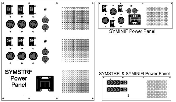
| Symmetra® Electrical Output Connections | ||||
| The Symmetra® system comes with various electrical output options. The options that are available are dependent on the frame model you choose. To determine the electrical connections on the Symmetra, please refer to the following table and diagram. | ||||
|
||||
| Voltage System | 8kVA max | 16 kVA max |
| 208/240 VAC USA configuration | SYMINIF | SYMSTRF |
| 208/240 VAC w/ PDU USA configuration | SYMINIF-PD | SYMSTRF-PD |
| International configuration single phase input | SYMIMIFI | SYMSTRFI |
| International configuration 3-phase input | SYMINIF3I | SYMSTRF3I |
|
||||
|
||||
 |
||||
|
||||
|
||||
| The Symmetra is hardwired for both input and output connections. The 230/240 Vac version includes an output power distribution panel at the rear of the frame and supports hardwired output. The 208/240 Vac version can be hardwired for output and also can be purchased with an optional output power distribution panel. (-PD) 5.1.1 The 208/240 Vac, 60 Hz Version
(USA configuration) 5.1.2 The 220/230/240 Vac, 50/60 Hz Version (International configuration) |
||||